We recently blogged about a project: ‘rebuilding a home, and changing the surrounding fields from dead agricultural land into an oasis of natural life’ – as well as building an off-grid electrical and heating system. Here’s the next in the series – about repairing an off-grid wind and solar electrical system.
Over to Andy:
Hi – it’s Andy Reynolds, author, forester, instructor, inquisitive repairer and promoter of self reliance, with another story of resourcefulness and the lack of it. I was called out to an off-grid system locally to give advice and maybe offer some repair assistance. I don’t advertise that I do this sort of thing as it can end up as a never-ending saga with people who are unwilling to learn, but luckily this was not so in this case. The caller had obtained my number through a mutual acquaintance so I thought, “see what happens”. As you may know, I’m the author of the Lowimpact book Wind and Solar Electricity, and we run a large renewable generation system at home. This has been built from as many recycled materials and components as possible over the last 25 years.
So I turned up at the property is question, down a rutty track, and to my mind it was a typical off-griddy type 0f place, running on a shoestring (I’m familiar with that).
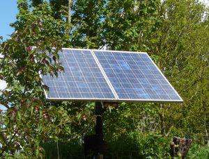
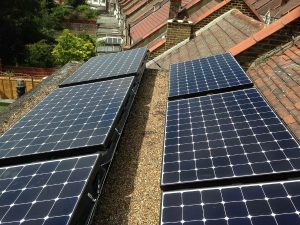
It took some time to get to somewhere near the bottom of the story. There were 4 solar panels on the roof of the cabin that looked about 100 watt each and a small turbine on a latcherty tower that was leaning at a decidedly unhelpful angle. Still there was something that with a positive attitude, could be the start of a system.

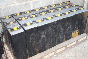
I was then shown the batteries in a large storage crate. They were not wired up and I was told they were probably not working. So it was time to test each of these components and to wire them up if the testing proved positive. The three batteries were large deep-cycle 12-volt units, about 20 kg each (and quite expensive). I used my ancient battery drop-tester to test the ability of the individual batteries to provide current. This needed to be done before they were wired up, so that a duff unit could be identified and isolated; however, all seemed surprisingly good.
Then on to the hydrometer to check the electrolyte specific gravity of each of the 6 cells within each the 12-volt batteries, and again they were all within an acceptable range. So it seemed we had good batteries that had been abandoned for whatever reason (sometimes it’s easier not to ask).

That was the end of the first visit; the second visit was to wire up the batteries, panels, and fit the new charge controller, as according to the owners, the original was faulty. I tested this later at home on a small 12v system and it was indeed faulty, overcharging during the day and discharging (without load attached) during the night. Maybe this was the original problem. I don’t recommend these cheap charge controllers as I have had several bad experiences. I either make my own as shown in my book or use Steca units. So the system was wired up and I really needed some sunny weather to test things – hence another visit was required (which was fine as the site was only a few miles away and I was interested to see the results).

Now on the third visit, the questions were: did the solar panels have the ability to charge the batteries; were they any good; and what about the existing wiring? This is where the short-circuit test comes in. This is basically putting a multi-meter set on DC 10 amps directly across the output of the panels. There’s a rule of thumb here to make sure your meter doesn’t ‘let the blue smoke dragon out’. Namely: make sure the potential current is less than the meter capacity, or break down the system into individual panels for testing. In this instance I used a clamp meter that will cover as wide a range as the current (amps).
The rest of that day is covered in this video and you can see the use of a clamp meter.
So we’d got to the point where the solar panels were feeding power into the batteries through a working charge controller. Now it was down to how the power was going to be used. The owners had a very small working (300 watt) inverter that could be connected to the battery terminals with crocodile clips (not ideal as corrosion can build up quickly). A bolted connection is much better – with a liberal coating of battery terminal grease. Still, for the purposes of experimentation we used the clips coated in grease, and 240v AC power was then available from the inverter.
The problem now was that of perception and understanding – by that I mean the owners knowing the level of charge in the batteries. A simple digital 12-volt DC meter was the answer, wired up into the kitchen so that a change in the battery volts could easily be seen (14 volts very good, 12.5 volts good, 12 volts not good, 11.8 volts very bad – do something).
There’s a whole raft of information and skills needed to manage lead-acid batteries. There’s a whole chapter in my book about this subject and I have a playlist (forklift batteries) on my channel.

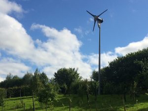
With that part of the system refurbishment complete it was then on to repairing the turbine. A brief inspection showed the rotor bearings were duff and the blade hub was loose on the shaft. The leaning tower was a small extendable lighting pole, normally used on work sites and quite unsuitable. The repair of the turbine is covered in two videos so there’s no need for me to explain this beyond saying that it was a full strip down and the windings had two coats of varnish applied to improve durability.
Once repaired, the turbine would need a better mounting. There was half a telegraph pole laid close by, so before leaving site I asked the owners to stand this upright with at least four feet of it sunk in the ground. This with the addition of a fabricated turbine mount that could be bolted at the top would be a half-decent substitute. I know it’s a bit short but a tall tower would be beyond expectations for this size of turbine in Lincolnshire with a low wind speed for most of the year. Ideally an extending lattice radio mast would be a good idea but even second-hand these can be expensive – not to mention the installation time.

A return visit to fit the turbine went smoothly and the turbine three-phase rectifier was mounted and connected. I then had time to check the system. All seemed good but I have doubts about all the connectors under the panels – those cheap MC4-type connectors frequently give trouble and I might end up removing them, soldering the joints and using heat-shrink insulation. The main lesson for would-be home solar installers is to have some background skills and knowledge. For owners of all sorts of systems maintenance is vital so take a word of advice from Flan O’Brien (The Third Policeman) “it is a great thing to do what is necessary before it becomes essential and unavoidable”. It is rare for professional solar installers to repair an existing DIY installation, they would just want to fit a new system for liability reasons. I was able to visit so many times as the site was reasonably close and on a route that I frequently take as part of general working life.
I will be hosting a half-day workshop for the Brighton Permaculture Trust in early October (2021) if you want that hands-on experience; otherwise check out the book and my YouTube channel.
I hope you enjoy the videos and gain knowledge from them – cheers.





2 Comments
Andy,
I bought your Wind and Solar Electricity book. It was very helpful to me when setting up my own solar off-grid system.
Would you advise me please on what you describe here as the range of voltages to assess the battery state, namely: “12.5V very good, 12V not good, 11.8V bad”?
Firstly, are these simply doubled for a 24V system? Secondly, does the battery need to be left to stabilise after full re-charge for a certain time before these measurements are taken?
I ask because:
I have a 1kWp solar array supplying 4x Varta LFD230 batteries wired together at 24V. There is a Tristar charge controller in-line. I monitor status with an analogue voltmeter and ammeter, and by qualitatively assessing how much power I use in relation to the size of the battery. I have a 400W inverter, but mostly use DC. All components were new in April.
My four batteries give me, I calculate, 460Ah (at 24V). So, at 50% I have access to a store of 230Ah or approx 5kWh. I assume that my battery is in a very good state because I use little energy (ca. 0.5kWh per day) and because the charge controller is mostly in float mode drawing hardly any amps. But I have a concern:
After sunset, with what I expect is a fully charged battery (voltmeter at 25.6V-ish), my family use about 0.1kWh. When we finish and I check the charge controller I see that it is showing a single yellow light which the manual says means 35 to 60% state of charge, and the voltmeter shows between 24.9 and 25.2V. I don’t understand why this should be because I have used only a hundredth of the power available.
In the morning, at sunrise, the bulk charge is less than an hour, then into PWM and float, which suggests to me that the battery needs little topping up.
So, is the yellow light telling me that the battery is not in as good a state as I think? Or is it that the charge controller is inaccurate? But, if so, why the ca. 25V reading on the voltmeter? hence my query about the values that you quoted in relation to a 24V system: is this voltage reading anything to worry about.
By the way, what do you think of those digital battery monitors? I’ve been told that they are not very good.
Best wishes,
Andrew
Andrew Rollinson, Hi, there’s a huge amount of info in the book, but to go back to basics with most renewable generation systems the power is both being used and generated at the same time. There is therefore no real time where a battery needs to stabilise. Working from the basic chemistry of a single lead acid cell the voltages vary from 2.6 v per cell when fully charged and being charged to 2.1 v per cell when power is being used and then to 1.85v per cell when discharged. You can work forward with these figures as a 24v system has 12 cells in series. Don’t get hung up on the yellow light work on voltage, that’s why we have a digital volt meter in our kitchen. You can see at a glance what is going on. Hope that clarifies things, cheers